Why Friction Torque Limiters Are Used
Friction torque limiters provide simple and cost effective protection of higher cost components from damage by preventing torque in excess of a specified amount from transmitting from one component to another.
Application Example: Torque Limiting Coupling
The illustration below shows a torque limiter which is used as a coupling between a power drill and nut which opens and closes a mud valve. When the valve reaches either a closed or open position, the torque limiter slips so that the valve is not overtightened and the operator’s back is not wrenched.
How a Friction Torque Limiter Works

- The torque setting of the unit is proportional to the compression of the disc spring which is controlled by the position of the torque adjustment nut.
- The pressure applied by the disc spring causes the drive plates to grip the friction pads.
- The friction pads transmit torque to the square socket via tabs that fit into slots in the sleeve.
- When the valve reaches either the closed or open position, the components colored GREEN and the friction pads experience torque that is higher than the pre-set amount of 15 foot pounds.
- The friction pads break away from the drive plates and these components will continue to slip against one another until the torque overload ceases. In this example, that would be when the drill is powered off.
PRODUCT PLACEMENT AND SELECTION EXERCISE: Preventing Overload of a Rotating Theater Element

An Oktoberfest performance features a 400 pound barrel which rotates on a turntable as Franz, Hans and Gunter play polka tunes. We want to assure that if anything would become wedged under the barrel or if a festival-goer decides to jump on for a ride, the barrel will stop rotating. From experience, the band knows that a person going around in circles after consuming large amounts of Bavarian beer will end in a mess. We also want to assure that neither the gearbox nor the motor will be damaged if these things occur.
Here is what we know about the drive system:
- 0.5 Horsepower 56C Motor
- 60:1 Reduction Through Gearbox
- 2:1 reduction from pulley mounted on output of gearbox to pulley mounted on the shaft which rotates the barrel.
- Safety Factor = 25%
Torque Required = ((HP of the motor x 63,000)/RPM of the driven shaft connected to the torque limiter) Safety Factor
| PLACEMENT OPTION #1 BETWEEN MOTOR & GEAR BOX |
PLACEMENT OPTION #2 OUTPUT OF GEAR BOX |
PLACEMENT OPTION #3 DRIVE SHAFT OF BARREL |
|
|
|
 |
 |
 |
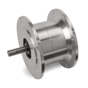
| T3C2H-56L NEMA Frame Torque Limiter
List Price = $570.00 |
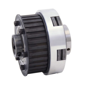
T5B2H-STL Pilot Mount Torque Limiter
List Price = $406.00 (without pulley) |
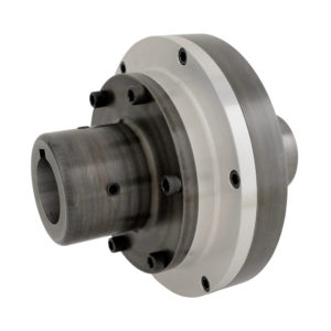
V6G1G-STL Torque Limiter Coupling
List Price = $1082.00 |
The most cost efficient choice would be option #2, placing the torque limiter on the output shaft of the gearbox. The timing belt pulley would be mounted to the pilot of the torque limiter. The torque limiter can be set at the factory or in the field to the required 1350 pound inches. At this setting, it has enough torque to handle the motor start-up torque and rotate the barrel while the motor is powered on. If an overload is experienced, the torque limiter will slip to disconnect rotation of the barrel and prevent transmittal of the torque overload into the gearbox.
Limitations of Friction Torque Limiters
It is important to fully understand how a mechanical friction torque limiter functions before making a selection and purchase. Below are the most important limitations to consider. In order to insure selection of a unit that will function as required, the review of all applications with Mach III engineering staff is recommended.
- Torque Settings Are Approximate
Mechanical friction torque limiters are not precision devices. Variances in torque may occur due to burnishing, temperature, humidity and wear. They are best suited to applications that can tolerate a variance in torque output of +/- 10%. - Mechanical Friction Torque Limiters Do Not Disengage Upon Overload
Friction torque limiters will continue to slip until the source of the torque overload is cleared or the machine is shut down. When the drive system is not directly monitored by an operator, another means of detecting the overload must exist. An example would be a sensor that measures the rotation of the output shaft. If the sensor does not detect rotation, it signals the control system to shut the motor off. - Mechanical Friction Torque Limiters Are Only Appropriate For Some Tension Control Applications
Torque limiters can be used effectively to maintain tension on a wire or filament when the torque requirement remains constant throughout the rewind or unwind process. When a small variation in torque output is required, friction torque limiters can customized with a hand-operated adjustment knob allowing an operator to vary the torque output on-the-fly. Narrow-web unwind and rewind applications, on the other hand, require higher speeds and higher variability in torque output. An example of this would be controlling the tension on the shaft which takes up the waste matrix on a label printing press. Pneumatically controlled brakes and clutches are typically a better choice for this type of tension control application.