Sometimes, a standard torque limiter simply won’t cut it. At Mach III, our engineers can create modifications of our standard catalog models for many applications — including critical medical equipment. For example, in the following application, we customized our miniature torque limiters for magnetic resonance imaging (MRI) machines. Designed as a retrofit, these units overcame challenges related to wear and backlash during operation.
Aluminum Torque Limiters Create OEM Headaches
We designed and delivered these custom torque limiters for a major original equipment manufacturer (OEM) in the healthcare field. The application required components with nonmagnetic materials, a long wear life and reliable, backlash-free operation.
At the time, the OEM was using aluminum Polyclutch® torque limiters, which incorporated very thin drive discs and 0.02-inch sintered bronze friction discs that wore into the aluminum sleeve, leading to excessive backlash. The torque limiters’ aluminum hub also wore on the shaft it was mounted on, causing additional backlash.
Custom Torque Limiters Feature Backlash-Free Design
 Our engineers overcame these challenges with a custom torque limiter that minimized backlash and provided a longer wear life. Featuring fewer components than the Polyclutch® units, our torque limiters incorporated stainless steel components, which reduced wear compared to the aluminum components. The design also included a Shrink Disc to attach the coupling to the shaft, eliminating a wear-prone keyed connection.
And finally, our engineers machined a thicker drive and friction discs from bronze bar stock. Using our lobed drive geometry, we then connected the drive and friction discs to the drive hub and coupling, respectively. This geometry has a lower tolerance compared to the traditional lug-style drive and friction discs that were used in the Polyclutch® design.
Thanks to these modifications, our custom torque limiters successfully overcame the medical OEM’s wear and backlash challenges. Our engineers can also customize brakes and torque limiters to meet various application requirements for water resistance, food safety and many more.
To learn more please visit our custom products webpage.
Although there are many instances in life where you want to avoid tension, sometimes you need it. For example, operations like printing, coating, laminating and converting depend on it to successfully process materials. Without constant web tension, issues like telescoping, dishing, wrinkling or web breaks can occur.
For these reasons, it’s important to make sure you’re not only maintaining constant web tension, but also controlling it. The right clutches and brakes can help.
Maintaining Web Tension
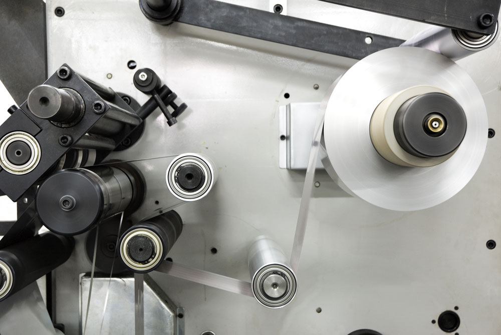
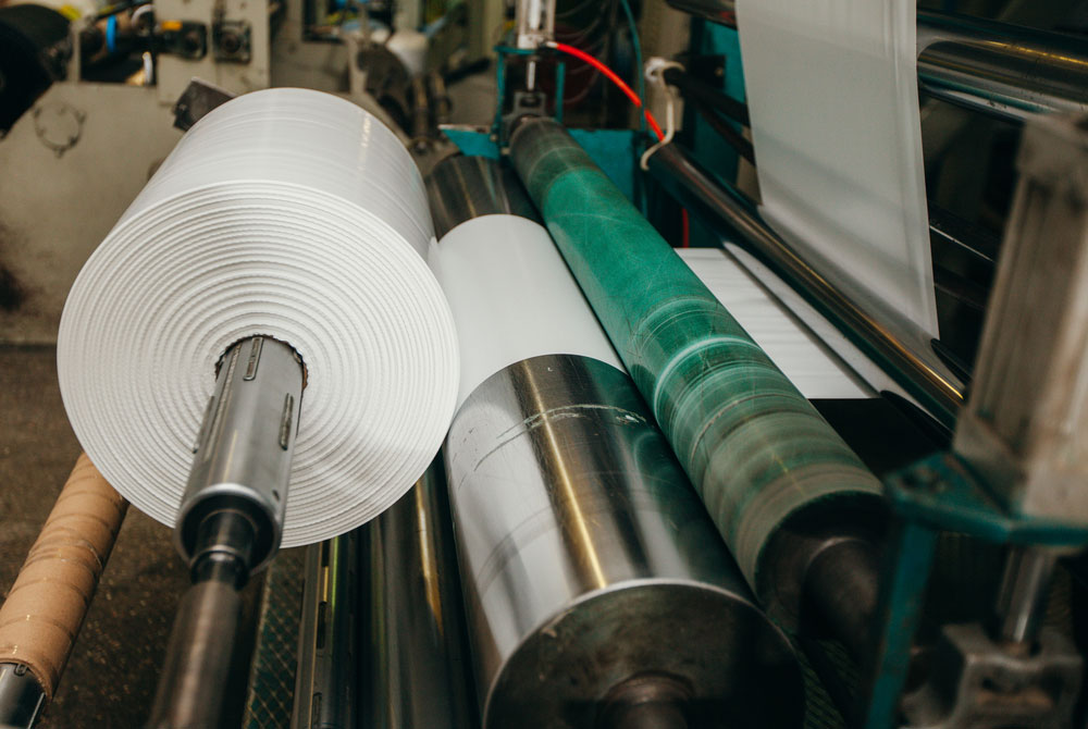
In these applications, torque is applied to the unwind roll to hold the web back, as well as to the rewind roll to pull the web forward, while additional intermediate drives between the unwind and rewind sections enable more complex machines to process materials at different tension values. Force must also be applied to the rewinds of any material that’s discarded — the matrix from a roll of labels, for example — during the converting process. And finally, force at the unwind and product and scrap rewinds is usually applied to the shaft on which the roll is mounted.
Brakes and clutches offer a common, cost-effective way to apply and maintain these forces. These components can be driven off the primary machine drive at a constant input speed. They maintain tension by applying the required torque to the unwind or rewind shaft, and then “slipping” to compensate for the speed difference between the constant input and the roll, which either increases (unwinds) or decreases (rewinds) in proportion to the roll diameter. This slipping occurs throughout the printing or converting process, causing friction and generating heat.
The following factors are important to consider when selecting brakes and clutches for web tension control, with the first two being the most important:
- Torque capacity: Can the brake or clutch handle the required torque output?
- Thermal capacity: Can the brake or clutch dissipate the heat that will be generated during the process?
- Sensitivity: How controllable is the torque within the required range?
- Smoothness: Will the clutch or brake apply force smoothly without pulsing or cogging?
- Maintenance: What is the expected life of the wear parts — friction pads, magnetic particles, etc. — and how difficult or expensive will maintenance be?
Selecting Your Clutch
Now you’re ready to select your clutch. Your first step is to determine the required torque range. For the rewind portion of the machine, the material on the roll builds during the process. As this happens, the torque required to maintain tension on the roll increases in a linear ratio. The torque output of the clutch must increase accordingly whether manually or automatically. To determine the required torque range, simply perform the following calculations:
1. Determine the required tension. Tension is measured in pounds per linear inch (PLI).
If the PLI is unknown, then:
PLI = Total Tension (pounds) / Web Width (inches)
For example, 0.5 PLI = 6.5 lbs / 13 in
If the PLI is known, then:
Total Tension (pounds) = PLI x Web Width (inches)
For example: 6.5 lbs = 0.5 PLI x 13 in
2. Next, calculate the required torque range.
Minimum Required Torque (lb-in) = Total Tension (pounds) x Radius at Core (inches)
For example: 19.5 lb-in = 6.5 lbs x 3 in
Maximum Required Torque (lb-in) = Total Tension (pounds) x Radius at Full Roll (inches)
For example: 156 lb-in = 6.5 lbs x 24 in
Unless your machine is dedicated to only one product, then you must also consider the PLI range, web widths, core and maximum roll diameters. Determine the required torque range for each product that will be processed on the machine.
Calculating Thermal Load
A clutch used on the rewind shaft is typically driven 5-percent higher at a constant input speed than the machine’s primary drive, which is expressed in rotations per minute (RPM). As the material feeds off of the machine and the roll diameter increases, the roll RPM decreases. Your clutch must compensate for the difference between the input and output RPM — 5 percent — by slipping. For the rewind section, this process is happening as the required torque increases. As a result, you only need one calculation to determine the thermal load.
Thermal load is expressed in thermal horsepower (Thp), but it can also be expressed in slip watts or kilowatts depending on the manufacturer:
Heat (Thp) = Full Roll Radius (In) / Core Radius (In) x Total Tension (Lb) x Linear Speed (FPM – feet per minute) / 33,000
For example: 0.39 Thp = 24 in / 3 in x 6.5 lbs x 250 fpm / 33,000
Learn More About Mach III Clutches
Be on the lookout for our next blog post which will explore how to select your brake to maintain and control web tension. In the meantime, you can learn about our standard clutches here.