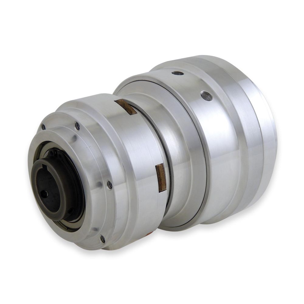
Air-Air Clutch-Brakes To Stop and Start the Shaft
Combination Air Applied Clutch and Air Applied Brake
Function: Starting and Stopping / Holding The Shaft
Drive Arrangement: Pilot Mounted Component to Shaft
Operation
- Applying air pressure engages the friction clutch or friction brake. Each requires a separate air signal.
- Torque of the clutch and brake is linear in response to air pressure applied.
Mounting
- Through (Mid) Shaft or End of Shaft.
- Clutch Brake slides on shaft and is fixed with set screws and a customer supplied key.
- Anti-rotation arm required to react, brake, and prevent rotation of the air housing.
- Clutch Brakes are designed for horizontal mounting. If vertical mounting is required, consult engineering for options.
Applications
- Stop/Start, Cycling, Indexing with input from a constantly driven sprocket or pulley.
- For applications with similar clutch and brake torque requirement.
- Maximum RPM varies by model and is listed on the PDF detail sheet (see table below). Consult engineering if the intended application exceeds the listed maximum RPM.
Design Features
- Clutch and brake combined in one unit for simplified mounting and control.
- Clutch brakes are bored to suit within the ranges shown on each product’s detail sheet (Imperial & Metric) for easy installation.
- Machined pilot for easy mounting of pulley or sprocket.
Customization Options
All Mach III products can be customized to meet the needs of your application.
" />| Product Code | Clutch Torque @ 80 PSI | Brake Torque @ 80 PSI | Maximum Bore with Standard Keyway | Detail Sheet | Request 3D CAD Model |
|---|---|---|---|---|---|
| Z3A1R-STH | 280 lb-in | 280 lb-in | 1.000 in (24 mm) | View PDF | Request |
| Z4A1R-STH | 611 lb-in | 611 lb-in | 1.250 in (31 mm) | View PDF | Request |
| Z5A1R-STH | 1,249 lb-in | 1,249 lb-in | 1.43 in (38 mm) | View PDF | Request |
| Z6A1G-STH | 2,868 lb-in | 2,868 lb-in | 2.000 in (52 mm) | View PDF | Request |